construction line inventor drawing
Is like a simplified version of XLINE. Specify a second point through which the construction line should pass.

How To Join Lines In Inventor Autodesk Community Inventor
The program includes several options in the Automatic C-line Creation dialog box to create horizontal or vertical construction lines.
. You could do the same thing with workplanes andor axes. Build snappable guide points and edges draw lines and primitive shapes in place automatically create faces in closed geometry precisely move duplicate and rotate geometry around a scene and cut-through meshes with extrude. Find Specify a point to define the root of the construction line.
Specify the angle of XLine Construction line. The ends can also be adjusted after you close the properties. The regular AutoCAD construction line functionality is still available via the XLINE command.
Tucked away under the additional tools portion of the Draw panel in the Ribbon youll find construction line in AutoCAD. Project the Y axis into your sketch this varies depending on what your sketch plane is. In this session you will learn How to draw Horizontal Vertical Angular Construction Lines.
The Neolithic also known as the New Stone Age was a time period roughly from 9000 BC to 5000 BC named because it was the last period of the age before wood working beganThe tools available were made from natural materials including bone hide stone wood grasses animal fibers and the use of waterThese tools were used by people to cut such as with the hand axe. Right-click in the drawing area to invoke a shortcut and select Angle. Pick Draw Construction Line.
This should work for most intersections. If you are in progress of creating the next route point right-click and select Done to quite the Route command. We also know it as an X-line command in auto cad.
Using AMTRCONT you can trace contours by using existing construction lines and circular. It is shown in the below image. When you do this youll see the Line command listed on the ribbon.
Type A on the command line or command prompt and press Enter. The steps to create an angle construction line are listed below. Press Enter to end the command.
Drawings for interior design projects generally use three line widths. In the IV help index look for sketches in drawings for more info. Next select a point on your drawing that is not connected to another point yet and press Enter or Return to start drawing a line from that point.
Cadalyst tip reviewer Brian Benton reminds us that AutoCAD has other line objects called construction lines or xlines and rays that we can use when making our drawings. Now dont get me wrong AutoCAD has so many tools that make drafting easier but every now and then a simple construction line can come in handy. If we draw the line directly after entering the command we will draw it freely if we check the command line we will find the different options mentioned before.
Purchase Autodesk Inventor from the Redstack online store today or learn more about Autodesk Inventor training course. Draws a line of infinite length. Construction lines can be created in an Autodesk Inventor design by sketching the line as you normally would and then select the construction line command.
If youre not already familiar with them AutoCAD has a couple of built in-tools to help you out. Figure 3-7 These are common line types used in drawings to describe objects hidden conditions and important relationships between components and space. Click to define the angle of Construction Line in Autocad.
To open the Construction Line command you need to click on little pop up menu called as Draw as shown by red arrow above. Guide edges and points allow for a construction workflow. In this article we will discuss this command and learn about handling different components of this command with an example.
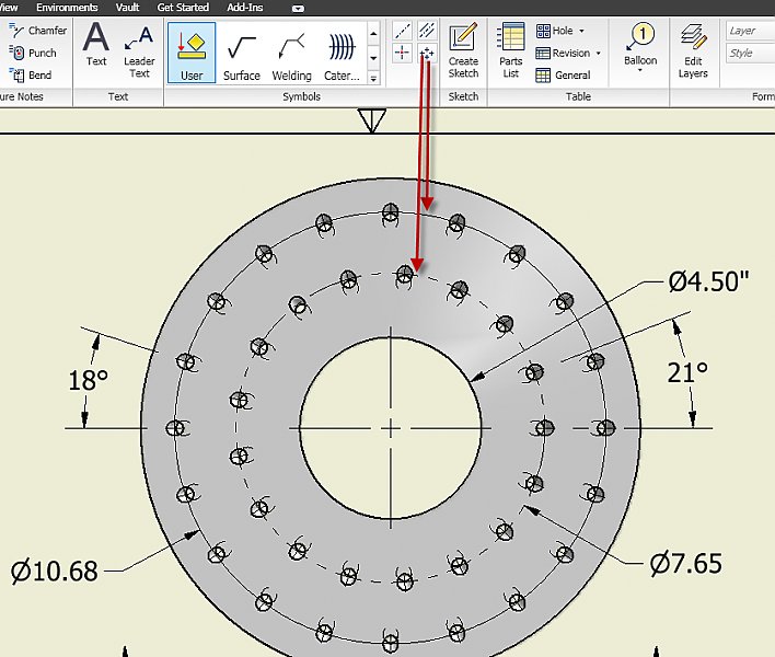
Construction Lines is a tool for accurate CAD style modelling. The through point you pick determines the space between the front and top views. If you are dimensioning to an intersection after placing the dimension open the properties dialog box and on the Display tab check the box for Enable intersection witness lines to show parametric witness lines.
Continue to specify construction lines as needed. Chapters are organized by SPUs lines of business and subject matter categories. To draw a line in AutoCAD you need to select the Line tool first.
Dimension it click Dimension click the line and then hover the mouse around until the ordinate icon shows up and you can dimension the length of this line add the angle. Then press to complete Xline. Click on the Construction Line icon as shown in the below image.
All subsequent xlines pass through the first point specified. When you use the AMAUTOCLINES command the program considers only objects on layers AM_0 AM_1 AM_2 AM_3 and AM_7. Make them a unconsumed sketch not part of the base sketch then in the IDW right click on the view select show content then on the part right click and select show sketches.
Invoke the Endpoint osnap shown below left-click to use this as the Through point. Then click on Construction Line command as shown in red box above. No command line entry is required.
In the Model browser or graphics window right-click a sketched route point in the parametric. However the AutoCAD Architecture 2023 toolset construction line feature is designed to give you a more intuitive way of drawing construction lines based on the geometry of existing objects or linework. Or Type XL on the command line and press Enter.
You can also access it by pressing CtrlL on your keyboard. Click Home tab Draw panel Construction Line. Enter 45 as the angle.
Thick dark medium and thin light. Xlines or construction lines are lines that extend through two defined points in both directions onto infinity. When I am sketching inside AutoCAD I often use xlines and rays.
Construction line is one of the 2d commands which used as a reference line in our drawing for managing accurate parameters of our drawing. You now have these sketches visible. The Design Standards and Guidelines DSG include engineering requirements details specifications policies and procedures.
Or Select Ang option on the command line. The DSG help Seattle Public Utilities SPU Design Engineers Project Managers and Consultants perform engineering work for SPU. Water System Design Manual DOH Pub 331-123 Revised June 2020.
Draw your line at roughly the right lengthangle. Click on Construction Line command in Autocad. We can draw it free or set it to be horizontal vertical follow a certain angle be the bisector of an angle or be parallel to certain line.

Automate Standard Additional Notes In The Drawing Gear Drawing Drawings Technical Drawing

Autodesk Inventor Create New Axis Mechanicaleng Blog

Pin By Martin Ricardo Arraya On Technical Drawings Interesting Drawings Autocad Isometric Drawing Technical Drawing
Fusion 360 Center Line Hack Imaginit Manufacturing Solutions Blog
Sketch Object Properties Imaginit Manufacturing Solutions Blog
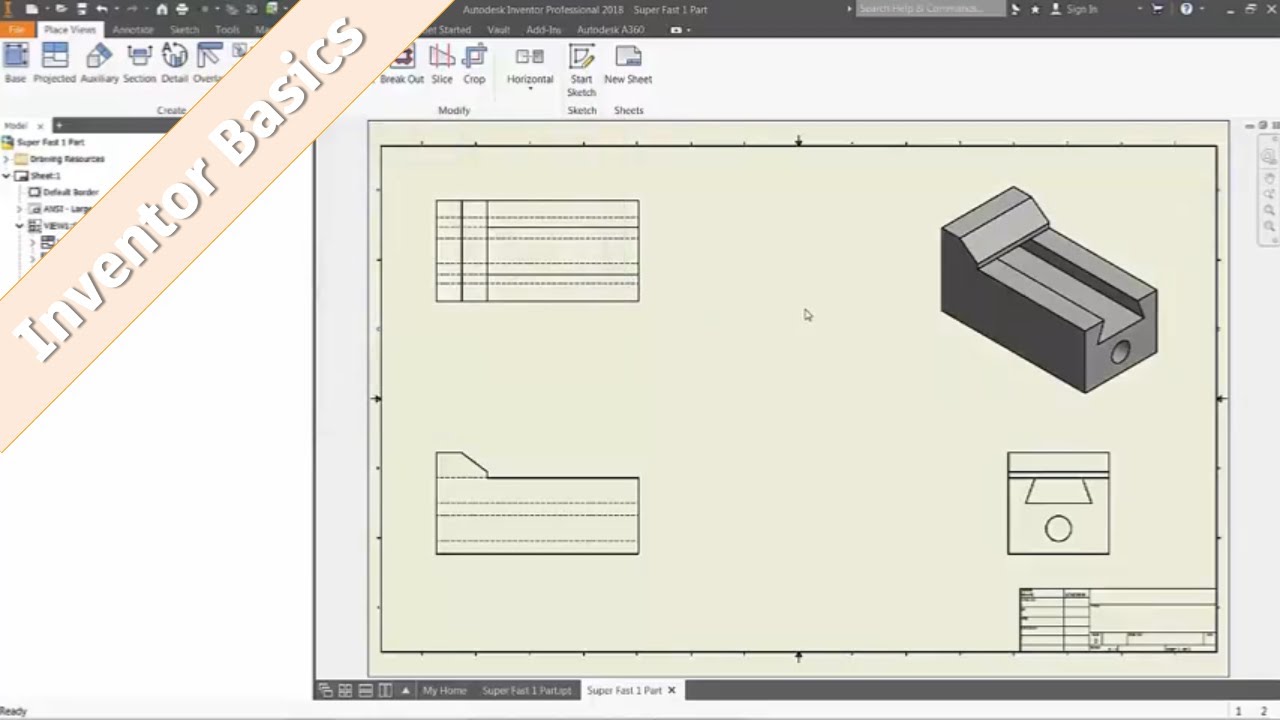
Inventor 101 Detail Part Drawings From 3d Cad Youtube
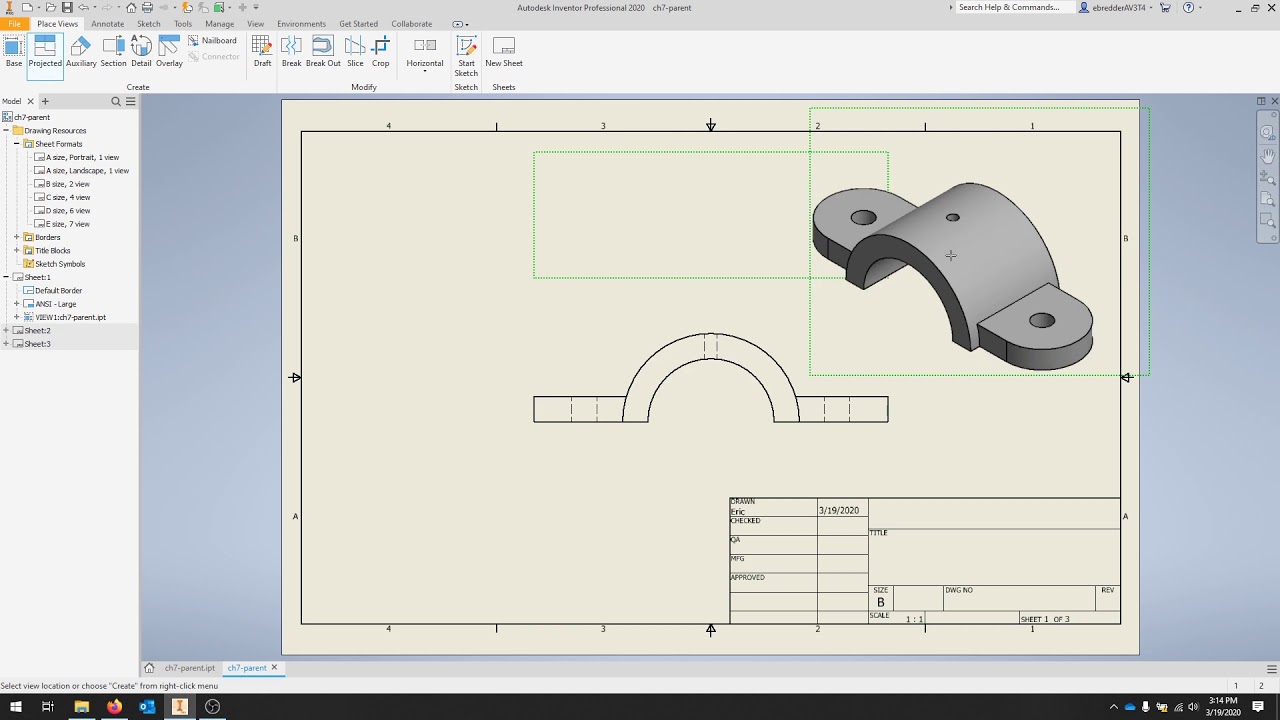
How To Make Drawings In Inventor Tutocad
Dimensioning Angles In An Idw Autodesk Inventor Autocad Forums
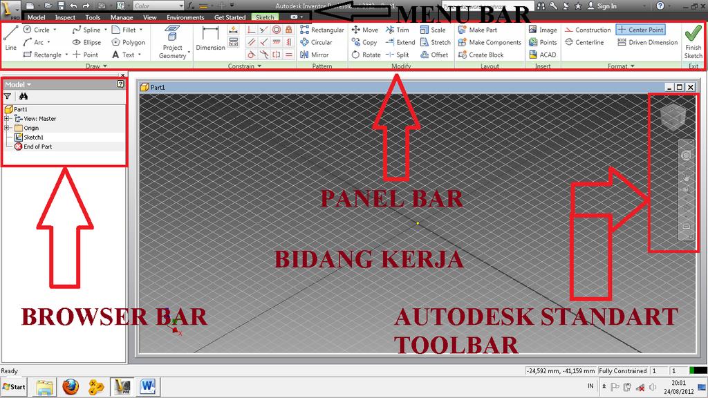
Autodesk Inventor Pengertian Dan Kegunaan Autodesk Inventor Pdf Free Download

Ten Useful Tips And Tricks For Autodesk Inventor 2021
Inventor Tip Using Construction Lines Arcs And Circles To Sketch Geometry Ascent Blog

Pin On 2d Cad Exercises

Solved Inventor 2019 Drawing Vertical Dimension To Circular Pattern Centerline Autodesk Community Inventor
Linear Diameters Quicker Drawings And Model Modification Imaginit Manufacturing Solutions Blog

Inventor Tutorial Using Construction Lines Video 11 Youtube

Solved Construction Lines Icon Missing Autodesk Community Inventor

Autocad Construction Lines Command Autocad Tutorial Youtube
2d 3d Get The Best Of Both With Autocad And Inventor By Autodesk University Autodesk University Medium

Solved Construction Lines Icon Missing Autodesk Community Inventor